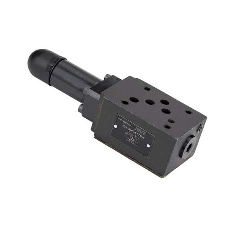
RETZ进口品质 ZDR6D叠加式减压阀
简要描述:RETZ进口ZDR6D、ZDR10D叠加式减压阀型阀是叠加式三通结构直动式减压阀。它对次级回路有减压功能.用于液压系统的减压
 品牌:RETZ美国瑞茨
- 工况条件:液压系统减压
- 温度/压力:P-T: 210bar@60℃
- 更新时间:2022/12/09
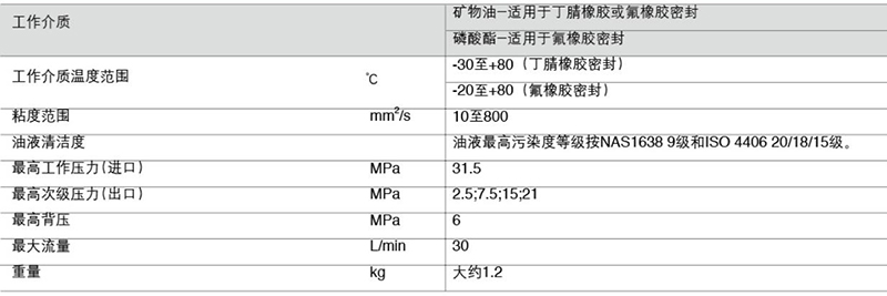
ZDR6D...30叠加式减压阀 技术参数 Technical paramete
通径(NG)6, 压力至21MPa ,流量至30L/min Diameter (NG) 6, pressure to 21MPa, flow to 30L/min
特性 Characteristic
叠加式结构 Superimposed structure
安装面符合DIN24340 A型和ISO 4401 Mounting surface in accordance with DIN24340 type A and ISO 4401
4种压力范围 4 pressure ranges
3种调节形式 3 types of adjustment
旋钮 knob
带保护罩的调节螺栓 Adjusting bolt with protective cover
带锁旋扭 Twister with lock
带压力表接口 With pressure gauge interface
可选择的单向阀 Optional check valve
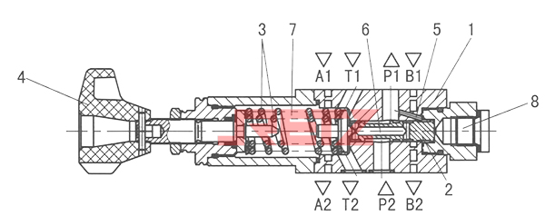
(ZDR6D、ZDR10D)进口叠加式减压阀 功能说明 Function description
该阀的组成包括阀体(1)、控制阀芯(2)、2个调压弹簧(3)、调压机构(4)和供选用的单向阀。The valve consists of a valve body (1), a control valve core (2), two pressure regulating springs (3), a pressure regulating mechanism (4) and an optional check valve.
在静止状态时.滑阀处于开启状态.油液可以自由的从油口P2流到油口P1(型号 "DP") .或者从油口A1流到油口A2(型号"DA")。油口P1的压力通过控制通道(5)作用于阀芯端面.与滑阀上的弹簧力互相平衡。如果油口P1的压力大于弹簧(3)的设定.阀芯(2)就会向弹簧方向移动 这样油口P1开口减小 使油口P1的压力为设定值。In the static state, the spool valve is open The oil can flow freely from port P2 to port P1 (model "DP") or from port A1 to port A2 (model "DA"). The pressure of oil port P1 acts on the end face of the valve core through the control channel (5) and is balanced with the spring force on the slide valve. If the pressure at port P1 is greater than the setting of the spring (3) The spool (2) moves towards the spring so that the opening of port P1 decreases and the pressure at port P1 is set.
如果受外力作用.使油口P1通道压力继续升高.阀芯(2)被推向弹簧(3)方向.此时油口P1的油液通过控制阀芯(2)的孔(6)返回油箱. 这是压力过高导致了回油。泄漏油经弹簧腔(7)通过T(Y)腔外泄。If an external force is applied, the channel pressure of oil port P1 will continue to increase. The valve element (2) is pushed to the direction of the spring (3). At this time, the oil at oil port P1 returns to the oil tank through the hole (6) of the control valve element (2) This is because the pressure is too high. The leaked oil leaks through the spring chamber (7) and T (Y) chamber.
"DA"型阀可选择装入一个单向阀.使A2到A1油路的油液能自由回流。压力表接口(8).可以安装压力表监测二次油路压力 The "DA" type valve can be optionally installed with a one-way valve so that the oil from A2 to A1 can flow back freely. Pressure gauge interface (8). A pressure gauge can be installed to monitor the pressure of the secondary oil circuit
使用注意∶由于存在内泄漏,当叠加式减压阀与叠加式(液控)单向阀 Note: Due to internal leakage, when the stacked pressure reducing valve and stacked (hydraulic control) check valve
成对使用时. 必须装在叠加式(液控)单向阀与换向阀之间 When used in pairs It must be installed between the stacked (hydraulic control) check valve and the directional valve
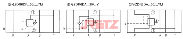
图形符号(①=阀侧;②=底板侧)
技术参数 Technical parameter
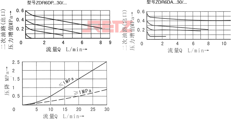
性能曲线(在使用HLP46,t=40℃±5℃时测得)
注∶设定压力较低时.性能曲线保持在相应的压力等级范围内。Note: When the set pressure is low, the performance curve shall be kept within the corresponding pressure rating range.
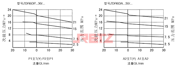
例∶如A2或P1口在10L/min时调定3MPa. 当二次压力增至3.6MPa时流量减小至趋于零 For example, if A2 or P1 port is set to 3MPa at 10L/min When the secondary pressure increases to 3.6MPa, the flow decreases to zero
ZDR6D...40叠加式减压阀 技术参数 Technical paramete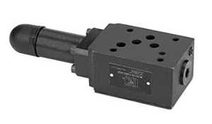
通径(NG)10, 压力至21MPa ,流量至50L/min Diameter (NG) 10, pressure to 21MPa, flow to 50L/min
特性 Characteristic
叠加式结构 Superimposed structure
安装面符合DIN24340 A型和ISO 4401 Mounting surface in accordance with DIN24340 type A and ISO 4401
4种压力范围 4 pressure ranges
3种调节形式 3 types of adjustment
旋钮 knob
带保护罩的调节螺栓 Adjusting bolt with protective cover
带锁旋扭 Twister with lock
带压力表接口 With pressure gauge interface
可选择的单向阀 Optional check valve
功能说明 Function description
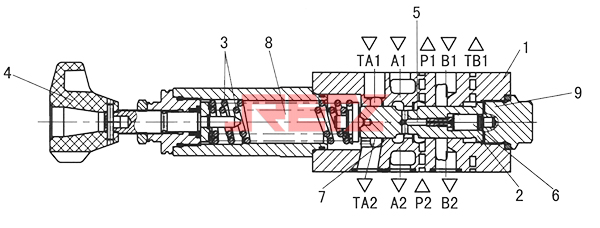
该阀的组成包括阀体(1)、控制阀芯(2)、1个或2个调压弹簧(3)、调压机构(4)和供选用的单向阀 The valve consists of a valve body (1), a control valve core (2), one or two pressure regulating springs (3), a pressure regulating mechanism (4) and an optional check valve
在静止状态时.滑阀处于开启状态.油液可以自由的从油口P2流到油口P1(型号 "DP") .或者从油口A1流到油口A2(型号"DA")。油口P1的压力通过控制通道(5)作用于阀芯端面.与滑阀上的弹簧力互相平衡。如果油口P1的压力大于弹簧(3)的设定.阀芯(2)就会向弹簧方向移动 这样油口P1开口减小 使油口P1的压力为设定值。In the static state, the spool valve is open The oil can flow freely from port P2 to port P1 (model "DP") or from port A1 to port A2 (model "DA"). The pressure of oil port P1 acts on the end face of the valve core through the control channel (5) and is balanced with the spring force on the slide valve. If the pressure at port P1 is greater than the setting of the spring (3) The spool (2) moves towards the spring so that the opening of port P1 decreases and the pressure at port P1 is set.
如果受外力作用.使油口P1通道压力继续升高.阀芯(2)被推向弹簧(3)方向.此时油口P1的油液通过控制边(7)返回油箱,这是压力过高导致了回油。泄漏油经弹簧腔(8)通过T腔外泄 If the channel pressure of oil port P1 continues to increase due to external force, the valve element (2) is pushed to the direction of spring (3). At this time, the oil at oil port P1 returns to the oil tank through the control side (7), which is caused by high pressure. The leaking oil leaks out through the spring chamber (8) through the T chamber.
"DA" 型阀可选择装入一个单向阀. 使A2到A1油路的油液能自由回流。压力表接口(9).可以安装压力表监测二次油路压力 The "DA" type valve can be optionally installed into a one-way valve The oil in A2 to A1 oil circuit can return freely. Pressure gauge interface (9). A pressure gauge can be installed to monitor the pressure of the secondary oil circuit.
使用注意∶Notes for use
1、由于存在内泄漏,当叠加式减压阀与叠加式(液控)单向阀成对使用时,必须装在叠加式(液控)单向阀与换向阀之间 Due to internal leakage, when stacked pressure reducing valve and stacked (hydraulic control) check valve are used in pairs, they must be installed between stacked (hydraulic control) check valve and directional valve
2、对于ZDR10DP和ZDR10D,TB1口的泄漏油经本阀上面的阀到达TA2口,因此.阀块(板)上必须开有TA口∶而对于ZDR10DB.TA1口泄漏油经本阀上面的阀到达TB2口,因此,阀块(板)上必须开有TB口 For ZDR10DP and ZDR10D, the oil leakage at TB1 port reaches the port TA2 through the valve above the valve, so the valve block (plate) must have a TA port: for ZDR10DB.TA1 port, the oil leakage reaches the port TB2 through the valve above the valve, so the valve block (plate) must have a TB port
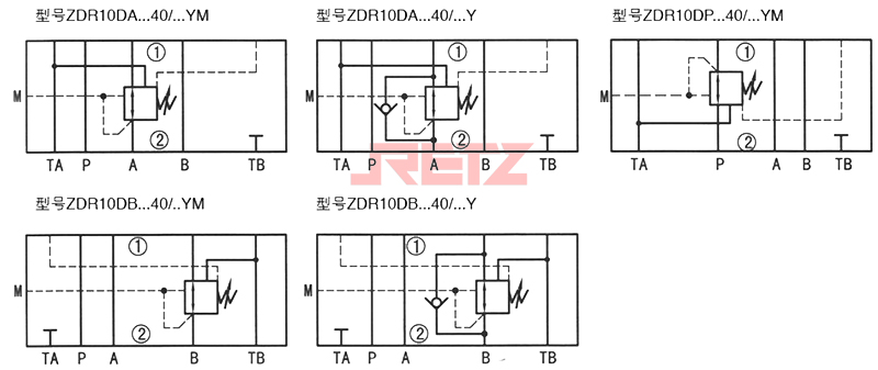
图形符号(①=阀侧;②=底板侧)
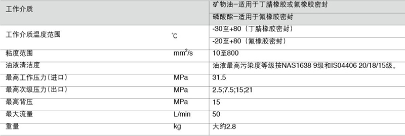
技术参数 Technical parameter
性能曲线(在使用HLP46,t=40℃±5℃时测得)
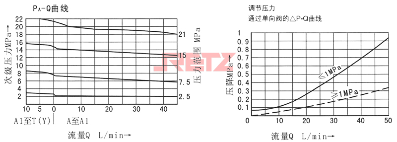
注∶设定压力较低时,性能曲线保持在相应的压力等级范围内 Note: When the set pressure is low, the performance curve will remain within the corresponding pressure rating range
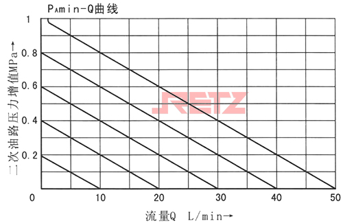
2.5MPa压力级的PAmin-Q曲线表明对应液流A1→A2和P2→P1 的最低设定与流量关系 The PAmin-Q curve of 2.5MPa pressure stage shows the relationship between the minimum setting and flow of corresponding liquid flows A1 → A2 and P2 → P1
说明:例流量20L/min时,A2口或P1 口调定为3MPa二次压力增加到3.4MPa时流量减少至趋于零 Note: For example, when the flow rate is 20L/min, A2 or P1 port is set to 3MPa, and the flow rate decreases to zero when the secondary pressure increases to 3.4MPa

 在线客服
在线客服