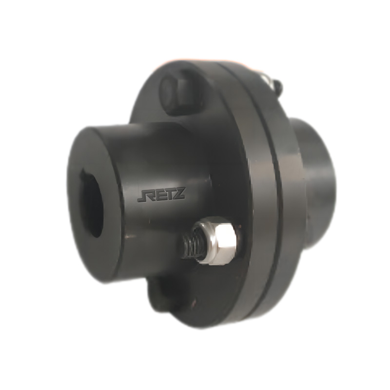
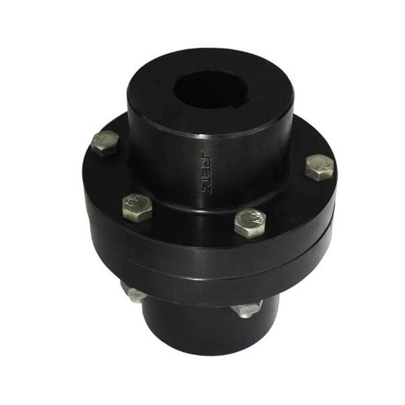
RETZ进口品质 YL凸缘联轴器
简要描述:RETZ进口凸缘联轴器(YL、YLD)属于刚性联轴器,是把两个带有凸缘的半联轴器用普通平键分别与两轴连接,然后用螺栓把两个半联轴器连成一体,以传递运动和转矩
 品牌:RETZ美国瑞茨
- 工况条件:联接机械
- 温度/压力:10-20000N.m.
- 更新时间:2023/03/28
进口凸缘联轴器(YL、YLD)产品用途 Product use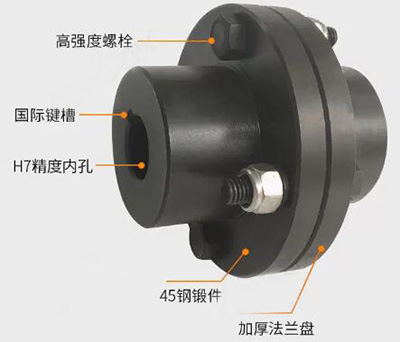
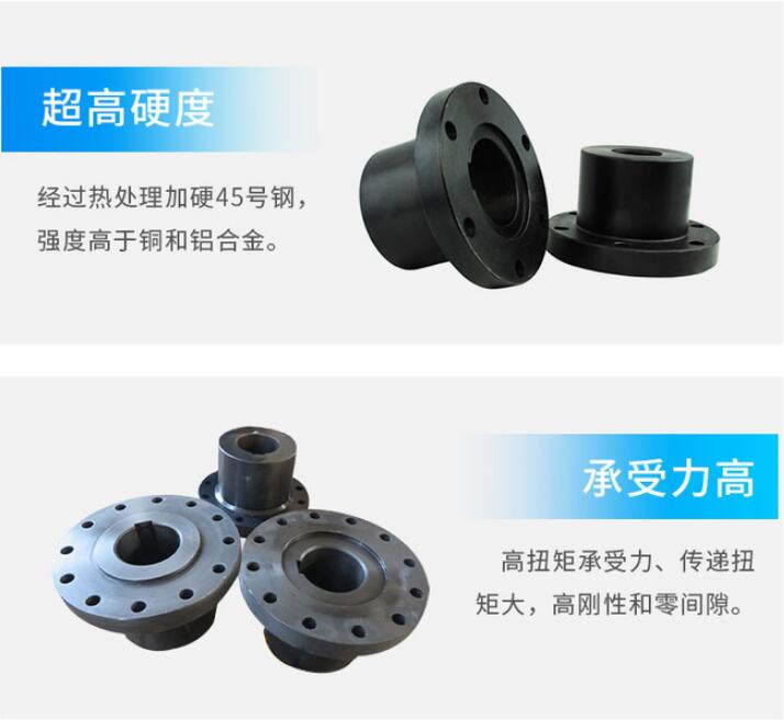
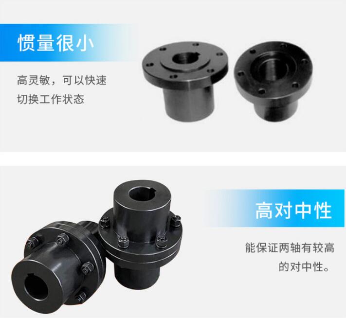
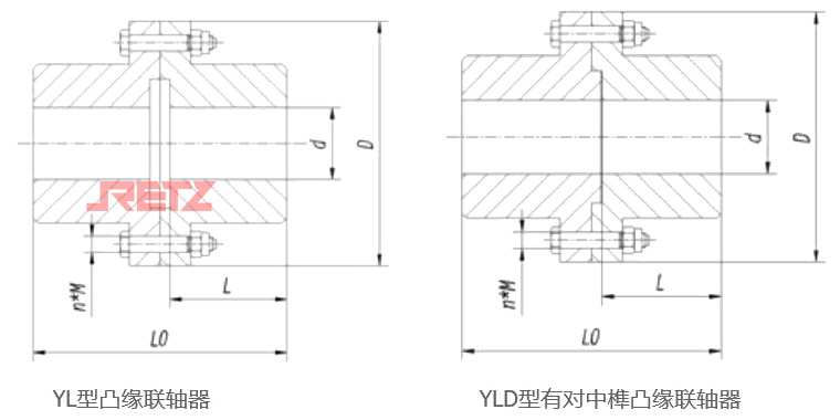
YL型凸缘联轴器可用灰铸铁或碳钢为材质,重载时或圆周速度大于30米/秒时应用铸钢或锻钢。本产品对两轴对中性的要求很高,当两轴有相对位移存在时,就会在机件内引起附加载荷,使工作情况恶化
YL type flange couplings can be made of gray cast iron or carbon steel, and cast or forged steel shall be used when under heavy load or when the circumferential speed is greater than 30 meters/second. This product has a high requirement for the neutrality of the two shafts. When there is relative displacement between the two shafts, additional loads will be caused within the machine, worsening the working condition
结构特点 Structural features
1.靠铰制孔用螺栓来实现两轴对中和靠螺栓杆承受挤压与剪切来传递转矩 Two-axis alignment is achieved by reaming holes with bolts, and torque is transmitted by the bolt rod withstanding compression and shearing
2.靠一个半联轴器上的凸肩与另一个半联轴器上的凹槽相配合而对中 Centering is achieved by matching the shoulder on one half coupling with the groove on the other half coupling
基本参数 Basic parameters and dimensions
型号 | 公称扭矩Tn | 许用转速 [n] | 轴孔直径d(H7) | 轴孔长度L | D | D1 | 螺栓 | L0 | 质量 | 转动惯量 | |||||
r/min | mm | 数量n | 直径M | ||||||||||||
N·m | 铁 | 钢 | 铁 | 钢 | Y型 | J、J1型 | mm | Y型 | J、J1型 | kg | kg·m2 | ||||
YL1 YLD1 | 10 | 8100 | 13000 | 10 | 10 | 25 | 22 | 71 | 53 | 3 (3) | M6 | 54 | 48 | 0.94 | 0.0018 |
11 | 11 | ||||||||||||||
12 | 12 | 32 | 27 | 68 | 58 | ||||||||||
14 | 14 | ||||||||||||||
16 | 16 | 42 | 30 | 88 | 64 | ||||||||||
18 | 18 | ||||||||||||||
19 | 19 | ||||||||||||||
20 | 20 | 52 | 38 | 108 | 80 | ||||||||||
— | 22 | ||||||||||||||
YL2 YLD2 | 16 | 7200 | 12000 | 12 | 12 | 32 | 27 | 80 | 64 | 4 (4) | M6 | 68 | 58 | 1.5 | 0.0035 |
14 | 14 | ||||||||||||||
16 | 16 | 42 | 30 | 88 | 64 | ||||||||||
18 | 18 | ||||||||||||||
19 | 19 | ||||||||||||||
20 | 20 | 52 | 38 | 108 | 80 | ||||||||||
— | 22 | ||||||||||||||
YL3 YLD3 | 25 | 6400 | 10000 | 14 | 14 | 32 | 27 | 90 | 69 | 3 (3) | M8 | 68 | 58 | 1.99 | 0.006 |
16 | 16 | 42 | 30 | 88 | 64 | ||||||||||
18 | 18 | ||||||||||||||
19 | 19 | ||||||||||||||
20 | 20 | 52 | 38 | 108 | 80 | ||||||||||
22 | 22 | ||||||||||||||
— | 24 | ||||||||||||||
— | 25 | 62 | 44 | 128 | 92 | ||||||||||
YL4 YLD4 | 40 | 5700 | 9500 | 18 | 18 | 42 | 30 | 100 | 80 | 3 (3) | M8 | 88 | 64 | 2.47 | 0.0093 |
19 | 19 | ||||||||||||||
20 | 20 | 52 | 38 | 108 | 80 | ||||||||||
22 | 22 | ||||||||||||||
24 | 24 | ||||||||||||||
25 | 25 | 62 | 44 | 128 | 92 | ||||||||||
— | 28 | ||||||||||||||
YL5 YLD5 | 63 | 5500 | 9000 | 22 | 22 | 52 | 38 | 105 | 85 | 4 (4) | M8 | 108 | 80 | 3.19 | 0.013 |
24 | 24 | ||||||||||||||
25 | 25 | 62 | 44 | 128 | 92 | ||||||||||
28 | 28 | ||||||||||||||
30 | 30 | 82 | 60 | 168 | 124 | ||||||||||
— | 32 | ||||||||||||||
YL6 YLD6 | 100 | 5200 | 8000 | 24 | 24 | 52 | 38 | 110 | 90 | 4 (4) | M8 | 108 | 80 | 3.99 | 0.017 |
25 | 25 | 62 | 44 | 128 | 92 | ||||||||||
28 | 28 | ||||||||||||||
30 | 30 | 82 | 60 | 168 | 124 | ||||||||||
32 | 32 | ||||||||||||||
— | 35 | ||||||||||||||
YL7 YLD7 | 160 | 4800 | 7600 | 28 | 28 | 62 | 44 | 120 | 95 | 4 (3) | M10 | 128 | 92 | 5.66 | 0.029 |
30 | 30 | 82 | 60 | 168 | 124 | ||||||||||
32 | 32 | ||||||||||||||
35 | 35 | ||||||||||||||
38 | 38 | ||||||||||||||
— | 40 | 112 | 82 | 228 | 172 | ||||||||||
YL8 YLD8 | 250 | 4300 | 7000 | 32 | 32 | 82 | 60 | 130 | 105 | 4 (3) | M10 | 169 | 125 | 7.29 | 0.043 |
35 | 35 | ||||||||||||||
38 | 38 | ||||||||||||||
40 | 40 | 112 | 84 | 229 | 173 | ||||||||||
42 | 42 | ||||||||||||||
— | 45 | ||||||||||||||
YL9 YLD9 | 400 | 4100 | 6800 | 38 | 38 | 82 | 60 | 140 | 115 | 6 (3) | M10 | 169 | 125 | 9.53 | 0.064 |
40 | 40 | 112 | 84 | 229 | 173 | ||||||||||
42 | 42 | ||||||||||||||
45 | 45 | ||||||||||||||
48 | 48 | ||||||||||||||
— | 50 | ||||||||||||||
YL10 YLD10 | 630 | 3600 | 6000 | 45 | 45 | 160 | 130 | 6 (4) | M10 | 12.46 | 0.112 | ||||
48 | 48 | ||||||||||||||
50 | 50 | ||||||||||||||
55 | 55 | ||||||||||||||
— | 56 | ||||||||||||||
— | 60 | 142 | 107 | 289 | 219 | ||||||||||
YL11 YLD11 | 1000 | 3200 | 5300 | 50 | 50 | 112 | 84 | 180 | 150 | 8 (4) | M12 | 229 | 173 | 17.97 | 0.205 |
55 | 55 | ||||||||||||||
56 | 56 | ||||||||||||||
60 | 60 | 142 | 107 | 289 | 219 | ||||||||||
63 | 63 | ||||||||||||||
65 | 65 | ||||||||||||||
— | 70 | ||||||||||||||
YL12 YLD12 | 1600 | 2900 | 4700 | 60 | 60 | 200 | 170 | 12 (6) | M12 | 30.62 | 0.443 | ||||
63 | 63 | ||||||||||||||
65 | 65 | ||||||||||||||
70 | 70 | ||||||||||||||
71 | 71 | ||||||||||||||
75 | 75 | ||||||||||||||
— | 80 | 172 | 132 | 349 | 269 | ||||||||||
YL13 YLD13 | 2500 | 2600 | 4300 | 70 | 70 | 142 | 107 | 220 | 185 | 8 (6) | M16 | 289 | 219 | 35.58 | 0.646 |
71 | 71 | ||||||||||||||
75 | 75 | ||||||||||||||
80 | 80 | 172 | 132 | 349 | 269 | ||||||||||
85 | 85 | ||||||||||||||
— | 90 | ||||||||||||||
YL14 YLD14 | 4000 | 2300 | 4800 | 80 | 80 | 172 | 132 | 250 | 215 | 12 (8) | M16 | 350 | 270 | 57.13 | 1.353 |
85 | 85 | ||||||||||||||
90 | 90 | ||||||||||||||
95 | 95 | ||||||||||||||
100 | 100 | 212 | 167 | 430 | 340 | ||||||||||
— | 110 | ||||||||||||||
YL15 YLD15 | 6300 | 2000 | 3400 | — | 90 | 172 | 132 | 290 | 250 | 12 (6) | M20 | 350 | 270 | 89.59 | 2.845 |
— | 95 | ||||||||||||||
100 | 100 | 212 | 167 | 430 | 340 | ||||||||||
110 | 110 | ||||||||||||||
120 | 120 | ||||||||||||||
— | 125 | ||||||||||||||
YL16 YLD16 | 10000 | 1800 | 3000 | — | 100 | 340 | 290 | 12 (6) | M24 | 119.57 | 5.271 | ||||
— | 110 | ||||||||||||||
120 | 120 | ||||||||||||||
125 | 125 | ||||||||||||||
130 | 130 | 252 | 202 | 510 | 410 | ||||||||||
— | 140 | ||||||||||||||
YL17 YLD17 | 14000 | 1600 | 2600 | — | 120 | 212 | 167 | 380 | 330 | 12 (6) | M24 | 430 | 340 | 171.71 | 9.139 |
— | 125 | ||||||||||||||
130 | 130 | 252 | 202 | 510 | 410 | ||||||||||
140 | 140 | ||||||||||||||
150 | 150 | ||||||||||||||
— | 160 | 302 | 242 | 610 | 490 | ||||||||||
YL18 YLD18 | 20000 | 1400 | 2300 | — | 140 | 252 | 202 | 420 | 360 | 12 (6) | M30 | 510 | 410 | (263.85) | (17.883) |
— | 150 | ||||||||||||||
— | 160 | 302 | 242 | 610 | 490 | ||||||||||
注:Note:
1、联轴器质量和转动惯量是按材料为铸铁(括弧内为铸钢)最小轴孔、最大轴伸长度的近似计算值 The coupling mass and rotational inertia are approximate calculated values based on the minimum shaft bore and maximum shaft elongation of cast iron (cast steel in brackets)
2、联轴器许用转速是按材料为铸铁,许用线速度30m/s,钢许用线速度为50m/s的近似计算值 The allowable rotational speed of the coupling is an approximate calculated value based on the material being cast iron, the allowable linear speed being 30 m/s, and the allowable linear speed being 50 m/s for steel
3、螺栓数量,括号内为铰制孔用螺栓 The number of bolts is shown in parentheses as bolts for reaming holes
4、凸缘联轴器轴孔、键形式和尺寸按GB3852-1997《联轴器轴孔/键槽型式和尺寸》的有关规 The form and dimensions of flange coupling shaft holes and keys shall comply with the relevant regulations in GB3852-1997 "Types and Dimensions of Coupling Shaft Holes/Keyways"

 在线客服
在线客服