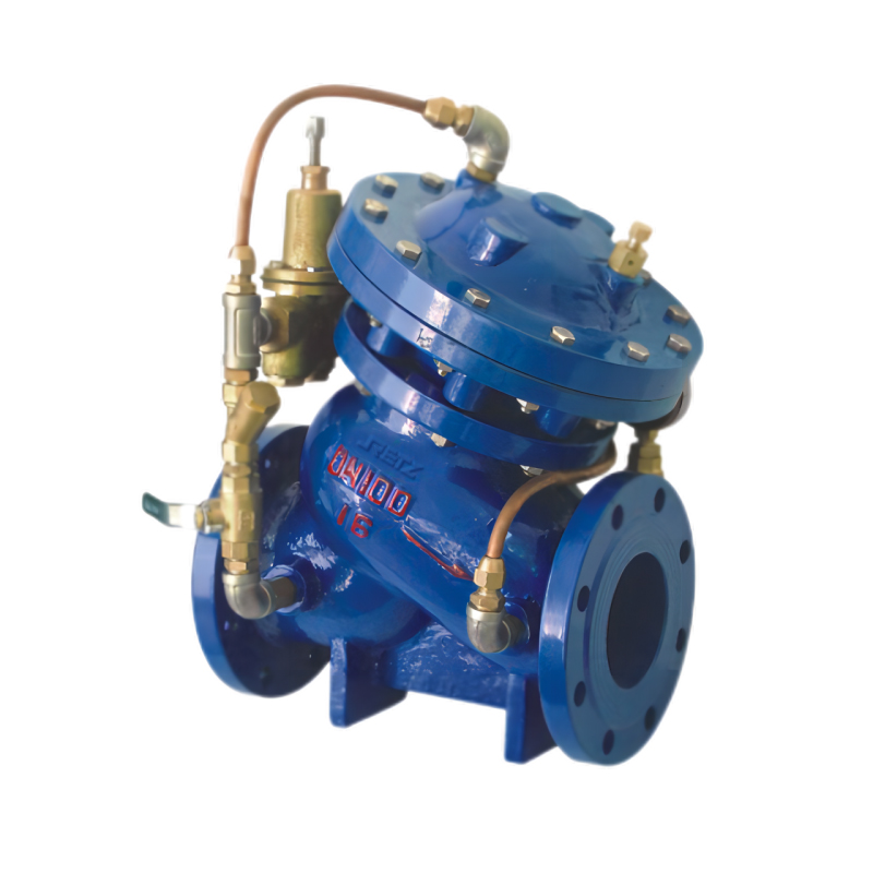
RETZ进口品质 隔膜式可调式减压阀
简要描述:RETZ进口隔膜式可调式减压阀用于高层建筑和工矿企业以及医药、食品等领域的管路系统中,将较高的上游压力降为符合要求的下游正常使用压力
 品牌:RETZ美国瑞茨
 - 工况条件:即可减动压,也可减静压
- 温度/压力:P-T: 25bar@100℃
- 更新时间:2023/04/16
产品描述 Product Description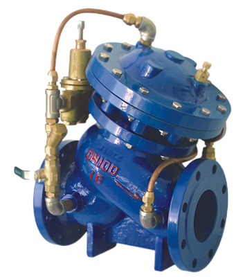
进口隔膜式可调式减压阀阀体采用了全通道流线型设计、流体阻力小、流量大。在传动方式上采用了水力自动操作,即利用管路中的水压自动控制主阀的动作,主要安装在高层建筑给水系统以及其它给水系统的管道上,将较高的上游压力降为符合要求的下游使用压力。
The imported diaphragm adjustable pressure reducing valve body adopts the full channel streamline design, with small fluid resistance and large flow. In terms of transmission mode, hydraulic automatic operation is adopted, which utilizes the water pressure in the pipeline to automatically control the action of the main valve. It is mainly installed on the pipelines of the high-rise building water supply system and other water supply systems, reducing the higher upstream pressure to the downstream service pressure that meets the requirements.
其特点如下 Its characteristics are as follows
1、减压效果可靠,出口压力不受进口压力及流量变化的影响,即可减动压,也可减静压 the decompression effect is reliable, the outlet pressure is not affected by the import pressure and flow changes, can reduce the pressure, can reduce the static pressure
2、调整操作方便。只需调节先导阀的调节螺钉,就能获得精确、稳定的出口压力 adjustment operation is convenient. Just adjust the adjusting screws of the pilot valve to obtain an accurate, stable outlet pressure
3、节能效果好。采用半直线型流道、宽阀体和等过流截面积设计,阻力小,压力损失小 good energy-saving effect. Adopt semi-linear flow channel, wide valve body and equal overcurrent cross-sectional area design, with small resistance and small pressure loss
压力等级:PN10(调节范围0.1-0.8MPa)
PN16(调节范围0.2-1.4MPa)
PN25(调节范围0.3-2.0MPa)
隔膜式:DN50~DN350
活塞式:DN50~DN800
工作原理 working principle
主阀安装在给水管路上,主阀盘是通过液压导管的压力传递,模仿导阀的动作。当下游压力低于设定压力时,导阀开启,隔膜上方的压力水被排放至下游,排放的速度大于进入的补充速度,主(围盘上移使下游压力增大到设定值。当下游压力达到设定值时,导阀关闭,隔膜在压力向下的作用下,使主阀盘下移,从而保持下游压力恒定。
The main valve is installed on the water supply pipe. The main valve disc is transferred through the pressure of the hydraulic catheter, imitating the action of the guide valve. When the downstream pressure is lower than the set pressure, the guide valve is opened, the pressure water above the diaphragm is discharged to the downstream, the discharge speed is greater than the replenishment speed of entry, the main (the coil up increases the downstream pressure to the set value. When the downstream pressure reaches the set value, the guide valve closes, and the diaphragm, under the downward action of the pressure, moves the main valve disc down, thus keeping the downstream pressure constant.
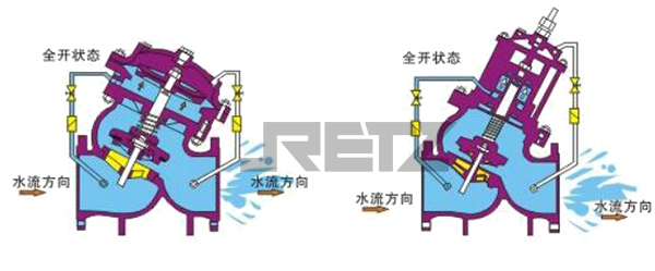
全开状态 Fully open state
当水泵启动后,阀门进水口压力上升,压力水一方面推动主阀板开启,另一方面通过导管系统进入膜片(活塞)下腔,而膜片(活塞)上腔的水通过导管系统泄入压力低的阀门出水口,而阀门在二合力的作用下缓慢开启。
After the water pump starts, the pressure at the valve inlet rises. On the one hand, the pressure water pushes the main valve plate open, and on the other hand, it enters the lower chamber of the diaphragm (piston) through the conduit system. The water in the upper chamber of the diaphragm (piston) is discharged into the outlet of the low pressure valve through the conduit system, and the valve slowly opens under the combined force of the two forces
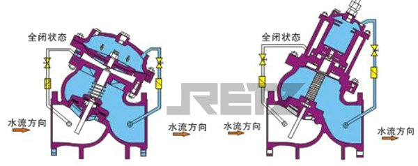
全闭状态 Fully closed state
当水泵停机后,阀门中的水流速度降低,在接于近零时,主阀板在弹簧力和自身重力作用下快速关闭,而阀后的压力水通过导管系统返回膜片(活塞)上腔,并推动固定阀杆上的小阀板缓慢关闭。
After the water pump stops, the water flow velocity in the valve decreases. When it is close to zero, the main valve plate quickly closes under the action of spring force and self gravity, while the pressure water behind the valve returns to the upper chamber of the diaphragm (piston) through the conduit system and pushes the small valve plate on the fixed valve rod to slowly close.
结构和主要零件材质 Structure and main component materials
该阀主要由主阀、过滤器、球阀和导管等组成。如下图所示 The valve is mainly composed of the main valve, filter, ball valve and catheter. As shown in the figure below.
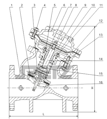
序号NO. | 零件名称Name | 主要材质Main Material |
1 | 阀体Valve Body | 铸铁、铸钢、不锈钢Cast lron, Cast steel,Stainless steel |
2 | 密封圈Sealing Ring | 丁晴橡胶Nitrite-butadiene Rubber(NBR) |
3 | 阀板Valve board | 球铁、铸钢Spheroidal Graphite Cast lron, Cast steel |
4 | 螺柱、螺母Plug,nut | 碳素钢Carbon steel |
5 | 小阀板Small Valve board | 铸钢、不锈钢Cast steel,Stainless Steel |
6 | 阀盖Bonnet | 铸铁、铸钢、不锈钢Cast lron, Cast steel,Stainless steel |
7 | 导向套Guide sleeve | 球铁、黄铜Spheroidal Graphite cast lron,Brass |
8 | 阀杆螺母Valve Stem nut | 碳素钢Carbon steel |
9 | 膜片Diaphragm | 丁晴橡胶Nitrite-butadiene Rubber (NBR) |
10 | 膜片压板Diaphragm Pressure Plate | 球铁、碳素钢Spheroidal Graphite Cast lron, Carbon steel |
11 | 导向套螺钉Screw to guide sleeve | 碳素钢Carbon steel |
12 | 膜片座Diaphragm seat | 铸铁、铸钢、不锈钢Cast Iron, cast steel, Stainless steel |
13 | 螺栓Bolt | 碳素钢Carbon steel |
14 | 阀杆Valve Stem | 不锈钢Stainless steel |
15 | 压缩弹簧Compression Spring | 不锈钢Stainless steel |
16 | 阀座Valve seat | 碳素钢、不锈钢Carbon steel, Stainless steel |
1.为了更有效地防止水锤的产生,水力控制阀将控制室设计成双腔体形式。根据不同的用途可以将两个腔室彼此隔离或相通,以实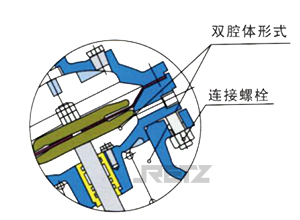 现缓开、缓闭或速闭等辅助功能。在一定程度上阻碍水锤的产生或功缓解水锤的力度,保护阀后的其他设备不受损坏。除此之外,阀盖与上腔室连为一体,使得阀盖、上腔室、阀杆、阀盘成为整体,只要松开阀体上的连接螺栓,即可将其一并取出,方便维修及更换易损件。
In order to more effectively prevent the generation of water hammer, the hydraulic control valve designs the control room in a dual chamber form. According to different purposes, two chambers can be isolated or connected to each other to achieve auxiliary functions such as slow opening, slow closing, or quick closing. To some extent, it hinders the generation of water hammer or alleviates the force of water hammer, protecting other equipment behind the valve from damage. In addition, the valve cover is connected to the upper chamber as a whole, making the valve cover, upper chamber, valve stem, and valve disc a whole. As long as the connecting bolts on the valve body are loosened, they can be taken out together for easy maintenance and replacement of vulnerable parts.
2.隔膜式水力控制阀阀杆两头导向的结构,采用中段长节距导向,避免了阀盖和阀座上的导向孔因加工或安装不同心,导致阀杆运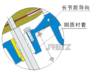 动受阻、易卡死现象,中段导向套与上阀体整体浇铸,加工精度得到保证,同时在与阀杆的接触面间加一铜质衬套,保护阀杆表面不被磨损、擦毛,使阀杆运动自如、平稳、灵活。
The structure of the diaphragm type hydraulic control valve stem is guided at both ends, adopting a mid section long pitch guidance, which avoids the phenomenon of the valve stem movement being blocked and easily stuck due to uneven machining or installation of the guide holes on the valve cover and valve seat. The mid section guide sleeve and upper valve body are cast as a whole, ensuring machining accuracy. At the same time, a copper sleeve is added between the contact surface with the valve stem to protect the surface of the valve stem from wear and burrs, making the valve stem move freely and smoothly flexible
3.隔膜式水力控制阀的阀盖、上腔室、阀杆、阀盘可整体取出,方便维修及更换橡胶密封面、O形环等易损件。阀盖与上腔室之间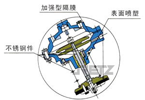 的隔膜采用尼龙网布加强型橡胶隔膜,耐剪切应力使用安全可靠。内件包括上腔式、阀杆、阀盘、弹簧、螺栓等,除了不锈钢件以外都进行了无毒喷塑处理,具有良好的防腐性能。
The valve cover, upper chamber, valve stem, and valve disc of the diaphragm hydraulic control valve can be taken out as a whole, making it convenient for maintenance and replacement of vulnerable parts such as rubber sealing surfaces and O-rings. The diaphragm between the valve cover and the upper chamber is made of nylon mesh reinforced rubber diaphragm, which is safe and reliable for shear stress resistance. The internal components, including the upper chamber, valve stem, valve disc, spring, bolt, etc., have undergone non-toxic spray molding treatment except for stainless steel parts, which has good anti-corrosion performance.
4.隔膜式水力控制阀的阀盘采用间隙组合结构,即阀杆和阀盘孔之间有一定的间隙;阀盘用螺钉和挡块相对固定在阀杆之间并留有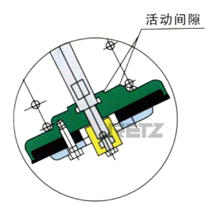 1-2毫米间隙,这样阀盘在垂直于阀杆的平面上有一定的自由度,可以弥补由于加工或装配误差造成阀座密封面与阀杆不垂直的缺陷,实现了零泄漏
The valve disc of the diaphragm hydraulic control valve adopts a clearance combination structure, that is, there is a certain gap between the valve stem and the valve disc hole; The valve disc is relatively fixed between the valve stem with screws and stop blocks, leaving a gap of 1-2 millimeters. This allows the valve disc to have a certain degree of freedom in the plane perpendicular to the valve stem, which can compensate for the defect of the valve seat sealing surface not being perpendicular to the valve stem due to machining or assembly errors, achieving zero leakage.
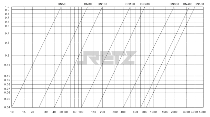
基本流量压差特性曲线图(Basic Flow and Differential Pressure Characteristic Graph)
安装与调试
安装
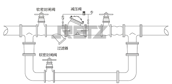
1、主阀应水平卧式安装,安装前要彻底清除管道内杂物。要注意主阀体外水流标示箭 头,要遵循方向安装。安装后应确保没有管路应力作用在阀体及阀内部件上。
2、主阀前要装一直闸阀和一只过滤器,主阀后也要装一只间阀,以便于维修。
3、主阀外装配管不以作吊装使用。
4、通水前必须彻底冲洗管路系统。
5、对重要给水管路应安装旁通阀。
6、过滤器要定期清洗。
调试
1、关闭上游隔离阀,开启下游隔离阀泄压使下游压力降低到0.1MPa左右,关闭下游隔离阀。
2、将导阀调节螺杆拧至最上方位置。
3、慢慢开启上游隔离阀至全开。
4、慢慢向下拧动导阀调节杆,使出口压力升高到设定值时将调节杆锁定,然后打开下 游隔离阀。

 在线客服
在线客服